"HAVE A NICE DAY:
I NEED TO PROGRAM A CFW500 USING WEGNOLOGY.
I WOULD LIKE TO KNOW HOW I CAN DO IT.
FOR EXAMPLE, I NEED TO CHANGE THE X PARAMETER FROM THE DASHBOARD. PLEASE HELP." 

"HAVE A NICE DAY:
I NEED TO PROGRAM A CFW500 USING WEGNOLOGY.
I WOULD LIKE TO KNOW HOW I CAN DO IT.
FOR EXAMPLE, I NEED TO CHANGE THE X PARAMETER FROM THE DASHBOARD. PLEASE HELP."
Hi Cristian!
Let us show you how to do this:
One way is to write the necessary parameters via modbus, then you must connect your VFD to an Edge device connected to WEGnology. We recommend using our Edge WCD-ED300 device.
In this example we will use the RS485 channel.
It is important that you know how information will flow from the dashboard to your device:
1 - We will use standard blocks in our dashboard.
2 - These blocks have a direct connection with the device (only for information, internally they use the topic “wnology/deviceID/command”).
3 - Finally, we will capture the command in an Edge Compute Workflow using one “trigger node” called “Device Command” and then use a “output node” called “Modbus Write” node to complete the process.
I am working on one example to change parameter P100 (Start Ramp) and I will post here as soon as I finish
Disclaimer: Technically, it is possible to send commands from the IoT application, as we will show below.
In this way, it is possible to change parameters and even activate machines.
However, the risk involved with a remote command must be considered.
In the same way that an operator activates equipment using one SCADA system, in a similar way, he can activate much more distant equipment, via IoT.
THEREFORE, IT IS THE RESPONSIBILITY OF THOSE PERFORMING THESE COMMANDS TO FOLLOW THE SAFETY RULES.
Obs.: Este tópico foi traduzido para o português na categoria “Dicas da Plataforma”:
1 - Requisites
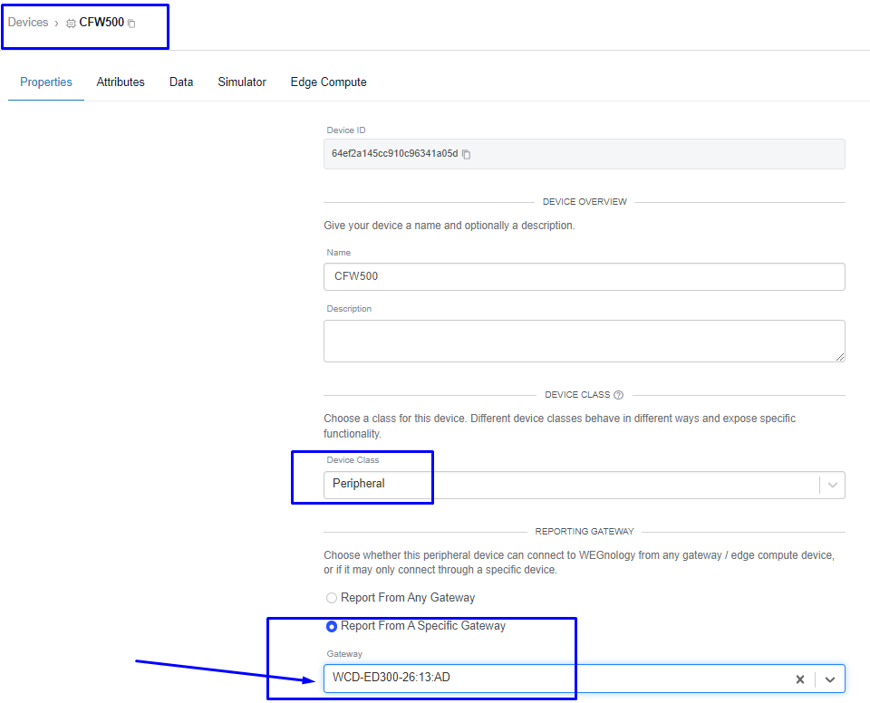
We need to have our 2 devices configured:
To know how connect our WCD-ED300 you can read the follow topic:
Remember that your Peripheral Device (CFW500) need to be associated to the Edge Compute Device (ED300)
2 - Editing the dashboard
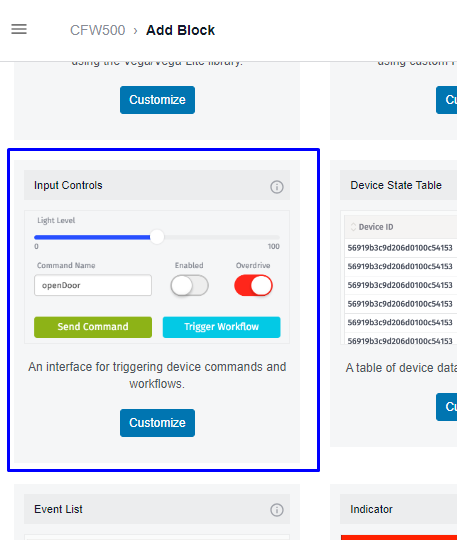
Insert one “Input Controls” block
In this block, we have some options, but in this case, we will use:
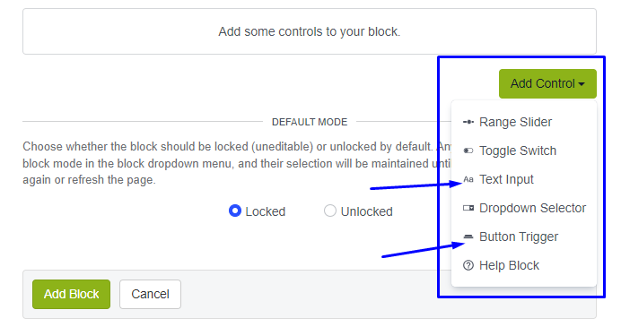
Our goal: a text Input and Send Button.
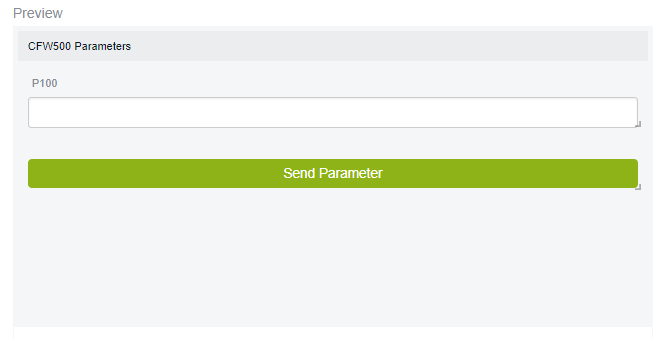
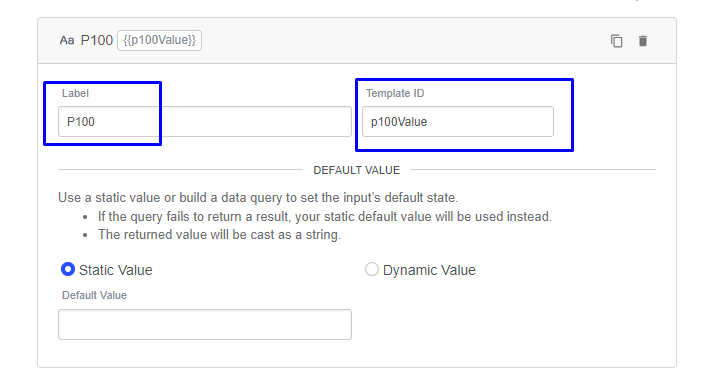
To the Text Input we have the important field “Template ID”, that we will use to send the value.
To the “Button Trigger” we have two options:
1 - Send command to the application workflow (cloud)
2 - Send command to the Device (edge). We need this option.
In this control, we have to select adjust the payload to contain our data thar we need to send.
For example, the text with a Ramp value (P100) from Input Text:
3 - Edge Workflow
Now we need to catch the command sent from dashboard to the device.
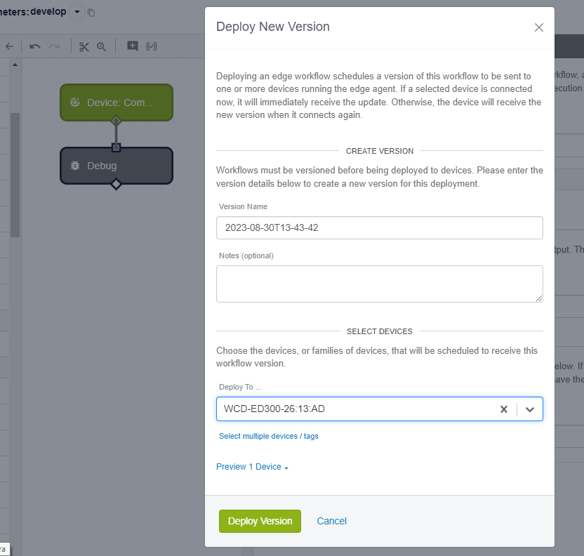
Create a “edge Workflow” with the trigger node: “Device Command”.
As we’ve done before in other tutorials, we can start only connecting one node and one debug node to see what’s happen:
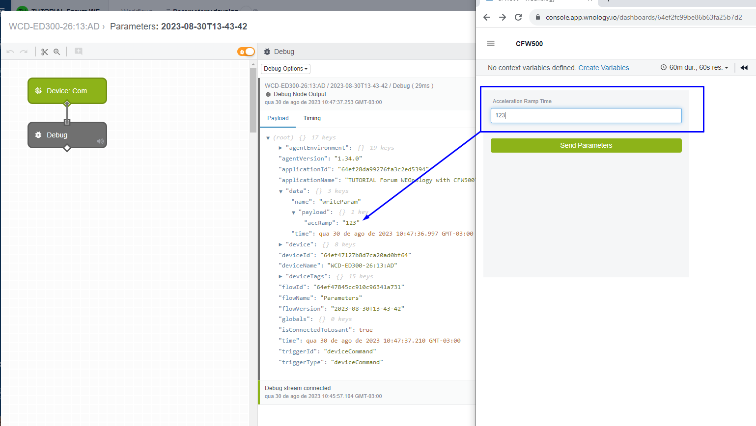
Before deploy the workflow, we can debug with live Look.
We can see bellow, that the value was sent to the device in the object “data.payload.accRamp”
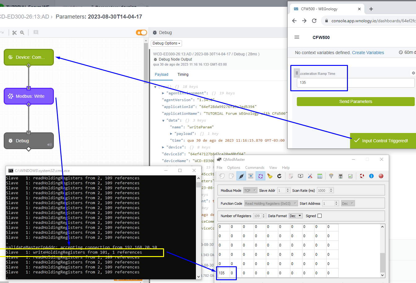
4 - Last Step, Modbus Write:
We need to use this value and send to our VFD using one “Modbus Write” command:
Note that we adjust the node with the number of register 100.
Because, all WEG Inverters use the same number of parameter as the Modbus register number.
For example: If you need to read the inverter output current Parameter P003, you need to read the holding register number 3.
We need to write P100, then we write to holding Register register number 100.
Now we have the whole flow of information, from the Dashboard to the equipment:
In my lab I used a Modbus TCP server, but it will work fine with Modbus RTU too